


Glocks & Glock Accessories
Shop Glockmeister
-
Sale Items
Sale Items
-
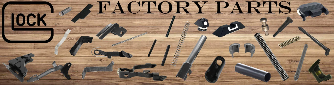
GLOCK OEM Parts
GLOCK OEM Parts
- Glock Magazine Parts
- GLOCK Receiver Parts
- MOS Adapter Sets and Plates
- GLOCK Slide Parts
- GLOCK 17T (Training) Specific Parts
- GLOCK 21SF Ambi Specific Parts
- GLOCK 36 Specific Parts
- GLOCK 42 Specific Parts
- GLOCK 43 Specific Parts
- GLOCK 43X, 48 Specific Parts
- GLOCK 43, 43X, 48 Specific Parts
- GLOCK 42, 43, 43X, 48 Specific Parts
- GLOCK 44 Specific Parts
- Gen5 Specific Parts
-
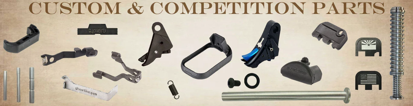
Glockmeister & Custom / Competition Parts
Glockmeister & Custom / Competition Parts
- Magazines & Loaders
-
GLOCK Receivers & Slides
GLOCK Receivers & Slides
- GLOCK Pistols
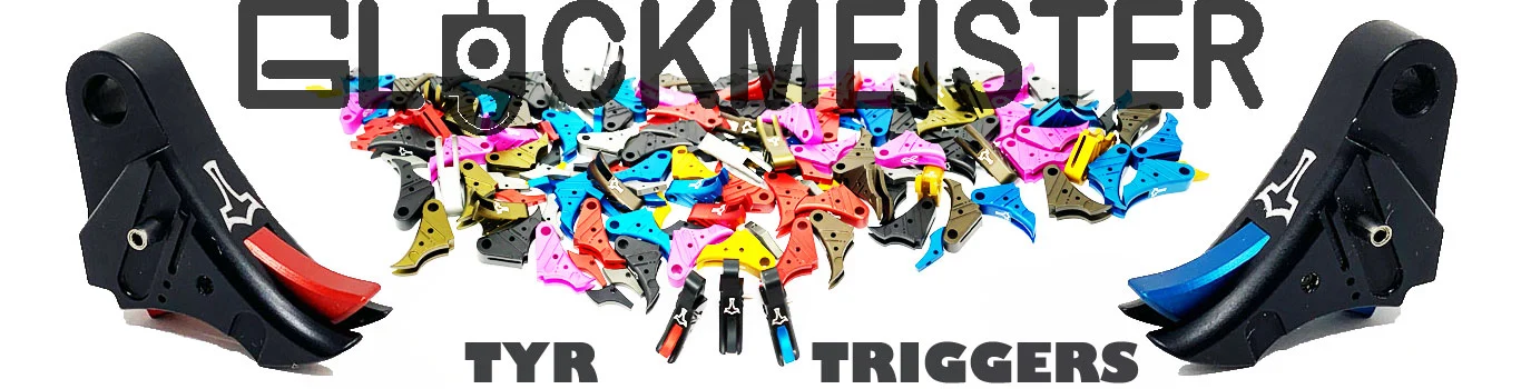
- Glockmeister TYR Triggers
- Grip Options
- Zorn Holsters
- Firearms
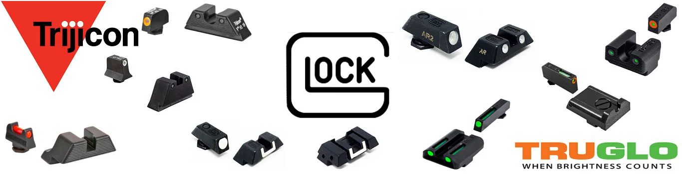
- GLOCK Sights
- Ammo
- Optics
- Accessories
-
Barrels
Barrels
-
Handgun Sights
Handgun Sights
FFL Finder
SPECIAL OFFERS
No Products in this catalog yet
Featured Products
No Products in this catalog yet
New products
No Products in this catalog yet